NCC 2022 Volume One - Building Code of Australia Class 2 to 9 buildings
Classification
Building class 1a Building class 1b Building class 2 Building class 3 Building class 4 Building class 5 Building class 6 Building class 7a Building class 7b Building class 8 Building class 9a Building class 9b Building class 9c Building class 10a Building class 10b Building class 10c

Filter

Classification
Building class 1a Building class 1b Building class 2 Building class 3 Building class 4 Building class 5 Building class 6 Building class 7a Building class 7b Building class 8 Building class 9a Building class 9b Building class 9c Building class 10a Building class 10b Building class 10c

F3

Part F3 Roof and wall cladding

Part F3 Roof and wall cladding

Introduction to this Part

This Part is intended to minimise the risk of water, including surface water and rainwater, entering the building and causing musty, damp and unhealthy conditions or damaging building elements by corrosion or other degradation. It is also intended to prevent water redirected away from the outside of the building damaging nearby properties.

Objectives

The Objective of this Part is to—

  1. safeguard occupants from illness or injury and protect buildings from damage caused by—
    1. ingress of water from outside the building; and
    2. the accumulation of internal moisture in the building.

F3O1 Objective

F3O1 aims to minimise the risk of occupant illness or injury, and protect buildings from being damaged, by ingress of water from outside the building and the accumulation of moisture within the building.

Functional Statements

A building is to be constructed to prevent penetration of water from the outside.

The construction of a building must prevent water from outside entering the building.

Performance Requirements

A roof and external wall (including openings around windows and doors) must prevent the penetration of water that could cause—

  1. unhealthy or dangerous conditions, or loss of amenity for occupants; and
  2. undue dampness or deterioration of building elements.

Limitations

F3P1 does not apply to—

  1. a Class 7 or 8 building where in the particular case there is no necessity for compliance; or
  2. a garage, tool shed, sanitary compartment, or the like, forming part of a building used for other purposes; or
  3. an open spectator stand or open-deck carpark.

Roofs and external walls to prevent water penetration

Roofs and external walls (including windows, doors and other openings within the external walls) must prevent water penetration which could cause dangerous conditions, loss of amenity or dampness and deterioration of building elements

Limitations

The limitations contain several exemptions to F3P1. These are based on the belief that the use and safety levels of the exempted buildings will not be significantly diminished by water entering them.

Limitation (a), regarding Class 7 and Class 8 buildings, refers only to such buildings which, in a particular case, do not exhibit any need for compliance with F3P1. Such buildings must be considered on a case-by-case basis. However, it is the responsibility of a building proponent to satisfy the appropriate authority that the exemption should apply.

Verification Methods

(1) Compliance with F3P1 for weatherproofing of an external wall is verified when—

  1. a prototype passes the procedure described in (2); and
  2. the external wall
    1. has a risk score of 20 or less, when the sum of all risk factor scores are determined in accordance with Table F3V1a; and
    2. is not subjected to an ultimate limit state wind pressure of more than 2.5 kPa; and
    3. includes only windows that comply with AS 2047.

(2) The test procedure referred to in (1)(a) must be as follows:

  1. The test specimen is in accordance with the requirements of (3).
  2. The test procedure is in accordance with the requirements of (4) or (5) as applicable.
  3. The test specimen does not fail the criteria in (6).
  4. The test is recorded in accordance with the requirements of (7).

(3) Test specimen: The test specimen must incorporate—

  1. representative samples of openings and joints, including—
    1. vertical and horizontal control joints; and
    2. wall junctions; and
    3. windows or doors; and
    4. electrical boxes; and
    5. balcony drainage and parapet flashings; and
    6. footer and header termination systems; and
  2. for a cavity wall
    1. a transparent material for a proportion of the internal wall lining (to provide an unobstructed view of the external wall cladding) with sufficient structural capability and similar air tightness to resist the applied wind pressures; and
    2. a 15 mm diameter hole in the internal wall lining below a window.

(4) The test procedure for a direct fix cladding wall or unique wall must be as follows:

  1. Apply 100% positive and negative serviceability wind pressures to the external face of the test specimen for a period of not less than 1 minute each.
  2. Apply static pressure of either 300 Pa or 30% serviceability wind pressure, whichever is higher, in accordance with the water penetration test procedure at clause 8.5.2 of AS/NZS 4284.
  3. Apply cyclic pressure in accordance with—
    1. the three stages of Table F3V1b; and
    2. the water penetration test procedure at clause 8.6.2 of AS/NZS 4284.

(5) The test procedure for a cavity wall must be as follows:

  1. Apply 100% positive and negative serviceability wind pressures to the external face of the test specimen for a period of not less than 1 minute each.
  2. Apply static pressure of either 300 Pa or 30% serviceability wind pressure, whichever is higher, in accordance with the water penetration test procedure at clause 8.5.2 of AS/NZS 4284.
  3. Apply cyclic pressure in accordance with—
    1. stage 3 of Table F3V1b; and
    2. the water penetration test procedure at clause 8.6.2 of AS/NZS 4284.
  4. To simulate the failure of the primary weather-defence or sealing, the following procedure must be applied to the test specimen:
    1. Insert 6 mm diameter holes through the external face of the cavity wall in all places specified below:
      1. Wall/window or wall/door junctions at ¾ height.
      2. Immediately above the head flashing.
      3. Through external sealing of the horizontal and vertical joints.
      4. Above any other penetration detail not covered by (A) to (C).
    2. Repeat the static and cyclic pressure tests of (b) and (c).
    3. Within 30 minutes of the completion of (ii), remove the internal lining of the cavity wall and check for compliance with (6).
    4. With the internal lining removed, apply a final static pressure test at 50 Pa for a period of 15 minutes.

(6) Compliance is determined as follows:

  1. A direct fix cladding wall and unique wall are verified for compliance with F3P1 if there is no presence of water on the inside surface of the facade.
  2. A cavity wall is verified for compliance with F3P1 if there is no presence of water on the removed surface of the cavity, except that during the simulation of the failure of the primary weather-defence or sealing, water may—
    1. transfer to the removed surface of the cavity due to the introduced defects (6 mm holes); and
    2. contact, but not pool on, battens and other cavity surfaces.

(7) The test report must include the following information:

  1. Name and address of the person supervising the test.
  2. Test report number.
  3. Date of the test.
  4. Cladding manufacturer’s name and address.
  5. Construction details of the test specimen, including a description, and drawings and details of the components, showing modifications, if any.
  6. Test sequence with the pressures used in all tests.
  7. For each of the static and cyclic pressure tests, full details of all leakages, including position, extent and timing.
Table F3V1a Risk factors and scores
Risk factor Category Risk severity Score
Wind region Region A0-5 (AS/NZS 1170.2) Low to medium 0
Region B1-2 (AS/NZS 1170.2)
Region C (AS/NZS 1170.2) High 1
Region D (AS/NZS 1170.2) Very high 2
Number of storeys One storey Low 0
Two storeys in part Medium 1
Two storeys High 2
More than two storeys Very high 4
Roof/wall junctions Roof-to-wall junctions fully protected Low 0
Roof-to-wall junctions partially exposed Medium 1
Roof-to-wall junctions fully exposed High 3
Roof elements finishing within the boundaries formed by the external walls Very high 5
Eaves width More than 600 mm for single storey Low 0
451-600 mm for single storey Medium 1
More than 600 mm for two storey
101-450 mm for single storey High 2
451-600 mm for two storey
More than 600 mm for above two storey
0-100 mm for single storey Very high 5
0-450 mm for two storey
Less than 600 mm for above two storey
Envelope complexity Simple shape with single cladding type Low 0
Complex shape with not more than two cladding types Medium 1
Complex shape with more than two cladding types High 3
As for high risk but with fully exposed roof-to-wall junctions Very high 6
Decks, porches and balconies None Low 0
Timber slat deck or porch at ground level
Fully covered in plan view by roof Medium 2
Timber slat deck attached at first or second floor level
Balcony exposed in plan view at first floor level High 4
Balcony cantilevered at first floor level
Balcony exposed in plan view at second floor level or above Very high 6
Balcony cantilevered at second floor level or above
Table Notes
  1. Eaves width is measured horizontally from the external face of any wall cladding to the outer edge of any overhang, including fascia and external gutters.
  2. Barriers to prevent falling and parapets are considered as 0 mm eaves.
Table F3V1b Cyclic pressure
Stage number Serviceability wind pressure (%)
Min Max
1 15 30
2 20 40
3 30 60

F3V1 Weatherproofing

F3V1 is a means to verify whether or not a proposed external wall achieves the requirements of F3P1, i.e. whether the wall prevents the penetration of water that could cause:

  • unhealthy or dangerous conditions or loss of amenity for occupants; and
  • undue dampness or deterioration of building elements.

F3V1 is not a mandatory component of the NCC; however, it is one form of assessment method that can be used to demonstrate compliance with the Performance Requirements.

Other assessment methods in the NCC include:

  • evidence to support that the use of a material, form of construction or design meets the Performance Requirement or a Deemed-to-Satisfy Provision;
  • comparison with a Deemed-to-Satisfy Provision where applicable; or
  • expert judgement, which means the judgement of an expert who has the qualifications and experience to determine whether a solution complies with the Performance Requirements.

The Verification Method must be applied in the following order:

  • confirm the limitations of F3V1(1)(b) are met;
  • develop a test specimen including representative samples of openings and the like (F3V1(3));
  • test the specimen in accordance with the relevant test procedure (F3V1(4) or (5));
  • assess the specimen against the compliance criteria (F3V1(6)); and
  • record the test results (F3V1(7)).

This process is shown in Figure F3V1a.

Figure F3V1a: Process for applying F3V1

Risk factors—Table F3V1a

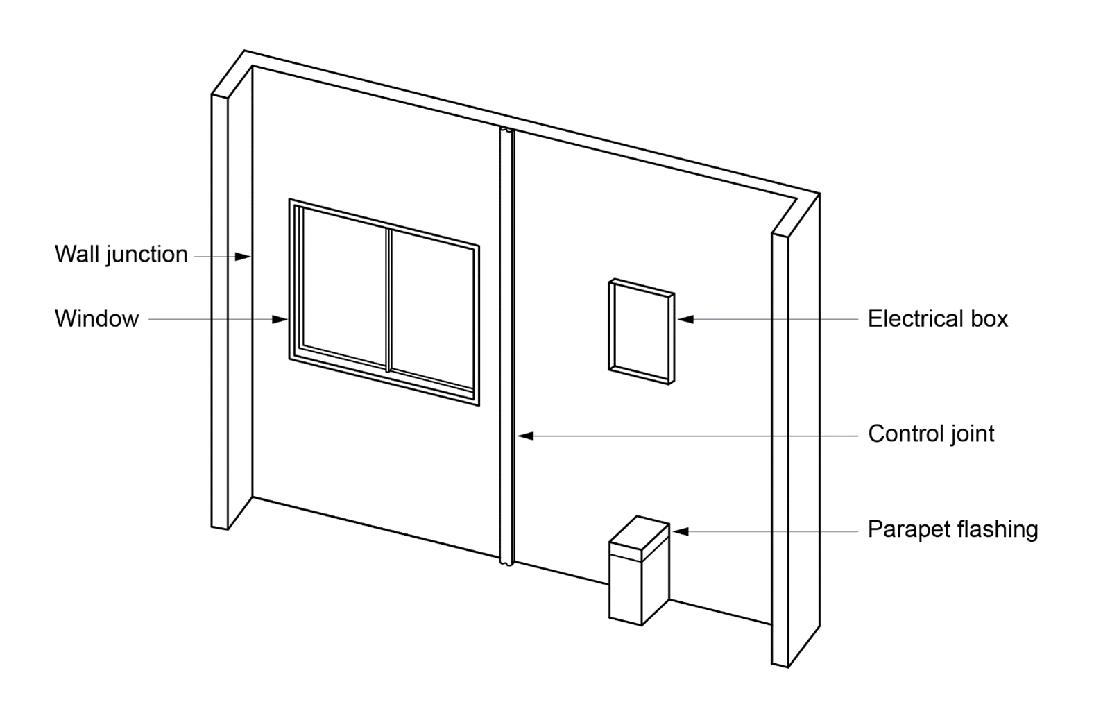
The risk score is determined by a number of factors including:

  • wind region;
  • number of storeys;
  • type of roof/wall junctions;
  • eave widths;
  • complexity of the building envelope; and
  • types of decks, porches and balconies.

The following are examples of typical roof/wall junctions and their associated exposureor protection categories:

  • a hip and gable roof with eaves is considered to have fully protected roof-to-wall junctions;
  • a hip and gable roof with no eaves is considered to have partially exposed roof-to-wall junctions;
  • parapets, enclosed barriers or eaves at greater than 90° to vertical with soffit lining are considered fully exposed roof- to-wall junctions; and
  • lower ends of aprons, chimneys, dormer windows and the like are considered roof elements finishing within the boundaries formed by the external walls.

Building envelope complexity is determined by the shape and the amount of cladding used. F3V1 includes both simple and complex shaped buildings:

  • A simple shaped building includes rectangular, L or T shaped buildings.
  • A complex shaped building includes a building with angular or curved shapes such as a Y shaped building.

Test specimen—F3V1(3)

Representative samples of openings and joints must be includedto test the whole cladding system. This includes samples of:

  • vertical and horizontal control joints;
  • wall junctions;
  • windows or doors;
  • electrical boxes;
  • balcony drainage(i.e. to prevent water pooling against the external wall) and parapet flashings; and
  • footer and header termination systems (i.e. a header termination system is where a cladding finishes at the top of a window).

A test specimenis illustrated in Figure F3V1b

Figure F3V1b: Illustration of a test specimen

Image
Figure F3V1b:	Illustration of a test specimen

Where a cavity wall is tested, a transparent material must be used in lieu of a portion of the internal wall lining. The transparent material will be used during the testing to observe any water penetration. To ensure an unobstructed view of the external wall occurs, other building components such as building membranes must be removed for the extent of the transparent opening within the internal wall lining. It should be noted that for the purposes of F3P1 building membranes are not a requirement. However, a membrane can be used to achieve compliance with F3V1.

The transparent material must be installed to maintain similar air tightness as the intended internal wall lining. To simulate the effects of power points, light switches and other similar openings which may cause air leakage, a 15 mm diameter hole must be placed in the internal wall lining below the window.

Test procedure—F3V1(4) and (5)

The test procedure requirements vary in relation to two sub-clauses. F3V1(4) specifies the test procedure for a direct fix cladding wall or a unique wall. F3V1(5) specifies the requirements for cavity wall construction. The difference betweenthe two sub-clauses is F3V1(5) has an additional water management test. This is due to cavity wall construction being designed to allow water to pass through the primary weather-defence (e.g. the skin of masonry on a masonry veneer wall), with the function of the cavity allowing for the removal of any water.

Direct fix cladding wall and unique wall—F3V1(4)

The test procedure for F3V1(4) contains three steps:

  • Apply a preconditioning loading to the external face of the wall, by placing 100% positive and 100% negative (suction) serviceability wind pressure to the external wall. The serviceability wind pressure will be determined by the location in which the wall is going to be installed. However, due to the limitations of the Verification Method, the ultimate state wind pressure can be a maximum of 2.5 kPa. For a vented cavity wall, the end sections of the cavity must be sealed and the material serving as the air seal must be able to withstand the same applied loading as the wall being tested.
  • Conduct a static pressure test at 30% of the serviceability wind pressure or 300 Pa, whichever is higher. F3V1(4)(b) refers to clause 8.5.2 ofAS/NZS 4284 for the requirements of this test.

Apply cyclic pressure and test the water penetration in accordance with clause 8.6.2of AS/NZS 4284, tested over the three stages specified in Table F3V1b.

Cavity walls—F3V1(5)

The test procedure for F3V1(5) contains four steps:

  • The first two steps are identical to F3V1(4) in respect to the preconditioning loading test and the static pressure test.
  • The third test, the cyclic pressure test, is slightly different to the cyclic pressure test in F3V1(4). The test is still required to be in accordance with clause 8.6.2 of AS/NZS 4284. However, instead of testing three stages of Table F3V1b, F3V1(5)(c) only requires one test, using serviceability wind pressures of stage three of Table F3V1a. Only one cyclic pressure test is required as the water management test in F3V1(5)(d) requires additional tests; one additional cyclic test and two additional static pressure tests.

F3V1(5)(d) contains the additional testing requirements for a cavity wall. This test represents the failure of the primary weather defence or sealing. The primary weather defence includes the wall material, any flashings and sealing of joints and openings.

Compliance—F3V1(6)

Similar to the test procedure, the compliance requirements are separated into two parts and are subject to the type of wall being tested.

F3V1(6)(a) specifies the compliance requirements for a direct fix cladding wall and a unique wall. Compliance for the testing of these types of walls is met by no presence of water to the inside surface of the facade. This includes the surface of the external wall which is fixed to the internal wall, or for a single skin wall, the internal wall.

The compliance requirements for a cavity wall in F3V1(6)(b) are different to the requirements for a direct fix cladding wall or unique wall. This is due to the purpose and nature of a cavity wall. Water which passes through the primary weather- defence will gradually be removed from the cavity either through weep holes or evaporation. F3V1(6)(b) therefore allows water to enter the cavity provided water is not present on the removed surface of the cavity. However, there are some exemptions to this, as the water may transfer to the removed surface through an isolated blemish due to the introduced defects. Also, water can contact cavity surfaces such as battens. However, it must be demonstrated that the water will be able to be removed from these surfaces.

The removed surface of the cavity will generally be the outer surface of the internal wall, for example,where the building membrane would be attached to a stud frame.

The purpose of the test report in F3V1(7) is to record the details and the outcomes of the test. This is common for any test procedure.

Deemed-to-Satisfy Provisions

(1) Where a Deemed-to-Satisfy Solution is proposed, Performance Requirement F3P1 is satisfied by complying with F3D2 to F3D5.

(2) Where a Performance Solution is proposed, the relevant Performance Requirements must be determined in accordance with A2G2(3) and A2G4(3) as applicable.

To clarify that the requirements of F3P1 will be satisfied if compliance is achieved with F3D2 to F3D5.

A roof must be covered with—

  1. roof tiles complying with AS 2049, fixed in accordance with AS 2050; or
  2. metal sheet roofing complying with AS 1562.1; or
  3. plastic sheet roofing designed and installed in accordance with AS 1562.3; or
  4. terracotta, fibre-cement and timber slates and shingles designed and installed in accordance with AS 4597, except in cyclonic areas; or
  5. an external waterproofing membrane complying with F1D5.

To prevent water penetration of roofs which could cause unhealthy and dangerous conditions or loss of amenity for occupants or dampness and deterioration of building elements.

Roofing materials and fixing methods

F3D2 contains reference to Australian Standards and other reference documents for a range of roofing materials and fixing methods suitable for the prevention of water penetration.

Sarking-type material used for weatherproofing of roofs and walls must comply with AS 4200.1 and AS 4200.2.

To prevent water penetration of roofs and walls which could cause unhealthy and dangerous conditions or loss of amenity for occupants or dampness and deterioration of building elements.

F3D3 Sarking

F3D3 references the Standard for sarking materials where sarking is required for weatherproofing roofs and walls (e.g. under roof tiles or on walls before weatherboards are fixed).

(1) Subject to (2) and (3), the following glazed assemblies in an external wall, must comply with AS 2047 requirements for resistance to water penetration:

  1. Windows.
  2. Sliding and swinging glazed doors with a frame, including French and bi-fold doors with a frame.
  3. Adjustable louvres.
  4. Shopfronts.
  5. Window walls with one piece framing.

(2) The following buildings need not comply with (1):

  1. A Class 7 or 8 building where in the particular case there is no necessity for compliance.
  2. A garage, tool shed, sanitary compartment, or the like, forming part of a building used for other purposes, except where the construction of the garage, tool shed, sanitary compartment or the like contributes to the weatherproofing of the other part of the building.
  3. An open spectator stand or open-deck carpark.

(3) The following glazed assemblies need not comply with (1):

  1. All glazed assemblies not in an external wall.
  2. Revolving doors.
  3. Fixed louvres.
  4. Skylights, roof lights and windows in other than the vertical plane.
  5. Sliding and swinging glazed doors without a frame.
  6. Windows constructed on site and architectural one-off windows, which are not design tested in accordance with AS 2047.
  7. Second-hand windows, re-used windows and recycled windows.
  8. Heritage windows.

To prevent water penetration via glazed assemblies of an external wall which could cause unhealthy and dangerous conditions or loss of amenity for occupants or dampness and deterioration of building elements.

F3D4 Glazed assemblies

F3D4 requires glazing in an external wall to complywith the AS 2047 requirements for resistance to water penetration. The provision does not apply to:

  • some Class 7 and 8 buildings;
  • garages, tool sheds, sanitary compartments and the like forming part of a building used for other purposes; and
  • open spectator standsand open-deck carparks.

F3D4(3) provides a list of glazing assemblies which do not need to comply with F3D4. AS 2047 does not cover these types of windows and therefore has been exempted as per the standard.

(1) External wall cladding must comply with one or a combination of the following:

  1. Masonry, including masonry veneer, unreinforced and reinforced masonry: AS 3700.
  2. Autoclaved aerated concrete: AS 5146.3.
  3. Metal wall cladding: AS 1562.1.

(2) The following buildings need not comply with (1):

  1. A Class 7 or 8 building where in the particular case there is no necessity for compliance.
  2. A garage, tool shed, sanitary compartment, or the like, forming part of a building used for other purposes, except where the construction of the garage, tool shed, sanitary compartment or the like contributes to the weatherproofing of another part of the building that is required to be weatherproofed.
  3. An open spectator stand or open deck carpark.

To prevent water penetration via external walls which could cause unhealthy and dangerous conditions or loss of amenity for occupants or dampness and deterioration of building elements.

F3D5 Wall cladding

F3D5 provides Deemed-to-Satisfy Provisions for the weatherproofing external wall cladding, offering specific methods based on the material used. If masonry is selected, including masonry veneer, unreinforced, and reinforced masonry, compliance with AS 3700 achieves weatherproofing requirements. Autoclaved aerated concrete is to adhere to AS 5146.3, while metal wall cladding needs to meet AS 1562.1.

If compliance with F3D5 is not met, a Performance Solution may be used to achieve compliance with the Performance Requirement.

F3D5(2) provides exemptions for certain building types. Class 7 or 8 buildings are exempt unless there's a specific need for compliance. Garages, tool sheds, and sanitary compartments are also exempt, provided they do not contribute to the weatherproofing of another part of a building that needs to be weatherproofed. Lastly, open spectator stands and open deck carparks are not required to comply with these provisions.